1.编译
从SDK的EXAMPLE目录复制任意一个示例到喜欢的目录下(这里我选择了uart_echo),
打开mingw32.exe定位到该目录,输入make开始编译,如果足够幸运的话最后会得到如下信息:
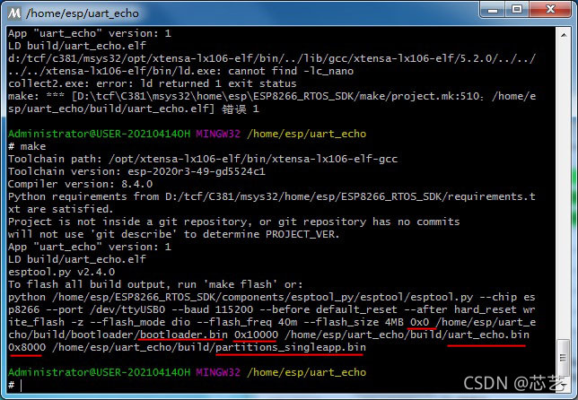
如红色标注的那样,生成的bin文件即为可执行程序,这里生成了三个,并给出了对应的烧录地址。
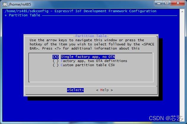
SDK将flash分区管理,在默认的分区模式下这三个文件是必须的,0X00地址处的是bootloader程序,是程序再次升级必须的,每次上电总是从这个地址处开始装入程序并运行,随后根据分区表跳转到用户程序。0x10000处是用户程序,就是你的程序加bootloader以外的所有功能都会链接到这个地址空间。0x8000地址处是分区表数据,也是不可或缺的。在项目配置菜单里这些均是可以设置的,默认的分区方案是Single factory app,no OTA ,如下图。在此方案下必须烧写的就是这三个文件,bootloader和分区表数据文件烧写一次后如果下次烧录时没有改变配置的话是无需再次烧录,仅烧录一个用户程序文件即可。
2.烧录
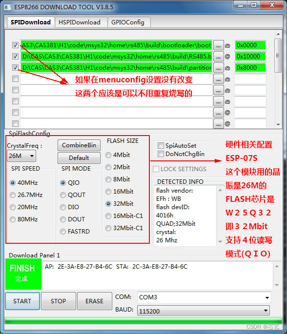
打开烧录软件(没有从乐鑫网站上找)将编译出的三个可执行程序一一填入,并设置好地址
点START按钮,ESP8266 在boot模式下上电即可开始下载程序。
3.运行测试
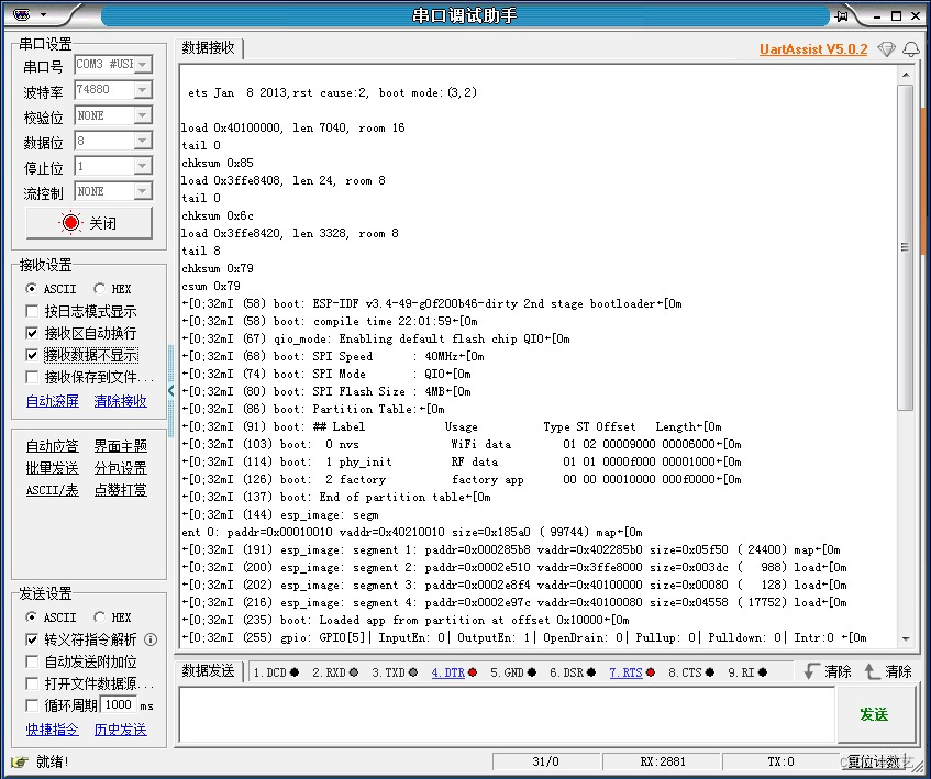
关掉电源,打开串口助手,非boot模式启动,结果如下:
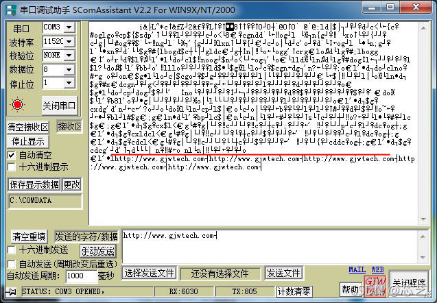
这里开始部分为SDK启动时输出的调试信息,由于启动时波特率和我的程序波特率不同输出了乱码,下面的部分为发送后的返回信息。
正如示例程序:
// Copyright 2018-2025 Espressif Systems (Shanghai) PTE LTD
//
// Licensed under the Apache License, Version 2.0 (the "License");
// you may not use this file except in compliance with the License.
// You may obtain a copy of the License at
//
// http://www.apache.org/licenses/LICENSE-2.0
//
// Unless required by applicable law or agreed to in writing, software
// distributed under the License is distributed on an "AS IS" BASIS,
// WITHOUT WARRANTIES OR CONDITIONS OF ANY KIND, either express or implied.
// See the License for the specific language governing permissions and
// limitations under the License.
#include <stdio.h>
#include <stdlib.h>
#include <string.h>
#include "freertos/FreeRTOS.h"
#include "freertos/task.h"
#include "driver/uart.h"
/**
* This is an example which echos any data it receives on UART0 back to the sender,
* with hardware flow control turned off. It does not use UART driver event queue.
*
* - Port: UART0
* - Receive (Rx) buffer: on
* - Transmit (Tx) buffer: off
* - Flow control: off
* - Event queue: off
*/
#define BUF_SIZE (1024)
static void echo_task()
{
// Configure parameters of an UART driver,
// communication pins and install the driver
uart_config_t uart_config = {
.baud_rate = 115200,
.data_bits = UART_DATA_8_BITS,
.parity = UART_PARITY_DISABLE,
.stop_bits = UART_STOP_BITS_1,
.flow_ctrl = UART_HW_FLOWCTRL_DISABLE
};
uart_param_config(UART_NUM_0, &uart_config);
uart_driver_install(UART_NUM_0, BUF_SIZE * 2, 0, 0, NULL, 0);
// Configure a temporary buffer for the incoming data
uint8_t *data = (uint8_t *) malloc(BUF_SIZE);
while (1) {
// Read data from the UART
int len = uart_read_bytes(UART_NUM_0, data, BUF_SIZE, 20 / portTICK_RATE_MS);
// Write data back to the UART
uart_write_bytes(UART_NUM_0, (const char *) data, len);
}
}
void app_main()
{
xTaskCreate(echo_task, "uart_echo_task", 1024, NULL, 10, NULL);
}
示例默认的波特率:74880 ,我把波特率改成了115200,(.baud_rate = 115200)
ESP8266上电复位后从片内ROM开始运行,晶振26M时波特率固定为74880,所以开始打印出的显示成乱码,等到用户程序运行后波特率设置为115200,开始显示用户程序发送的数据。
可以用支持 74880波特率的串口软件查看之前发送的信息
程序功能很简单,就是你发送什么esp8266就返回什么,一直循环。
|
|